Classification gives components a home and can be accompanied by naming conventions and/or guides.
Usage
- Create a map of your system, it has to fit your architecture
- Draw zones to make boundaries and name the areas, to make those boundaries visible
- Set rules/guidelines for each area
Those areas with rules/guidelines will form the component classification of your system. It will be individual to your system and it even can vary for multiple products from one company.
What you’ll find here is the methodology of atomic design and how this might be an orientation around which you can create your own classification and second step is how that is put into practice at the example of Hokulea design system.
Orientation
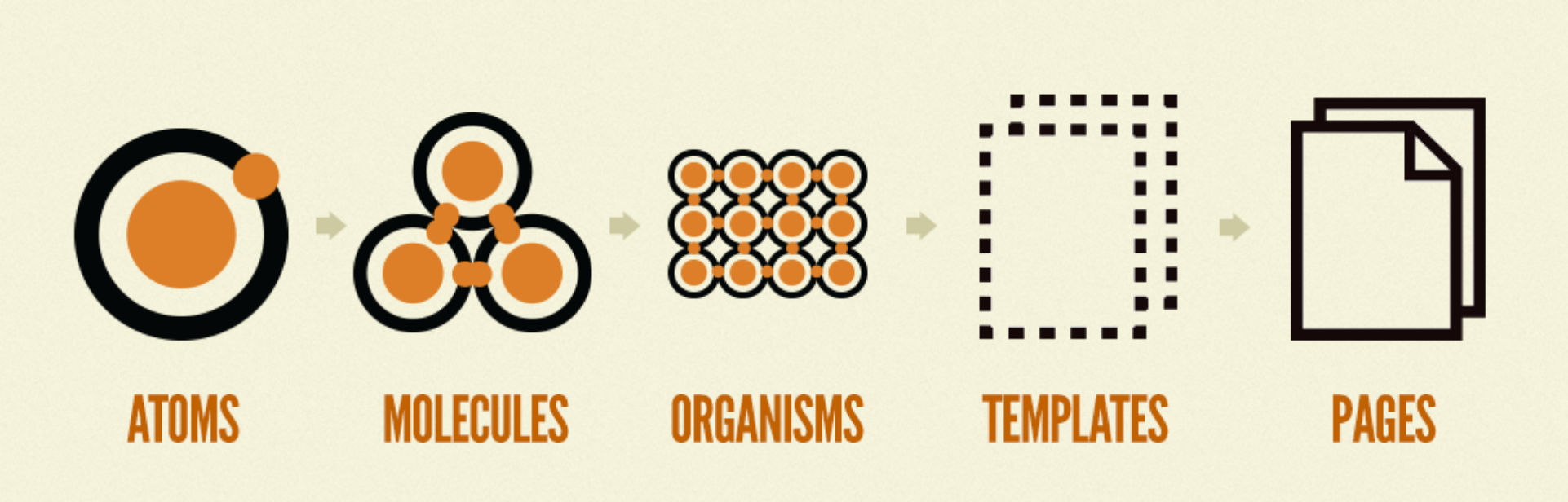
Atomic design is the first orientation, where components are ordered from small (atoms) to big (pages) and also stating that the next level is made up of components from the lower (see Figure 1).
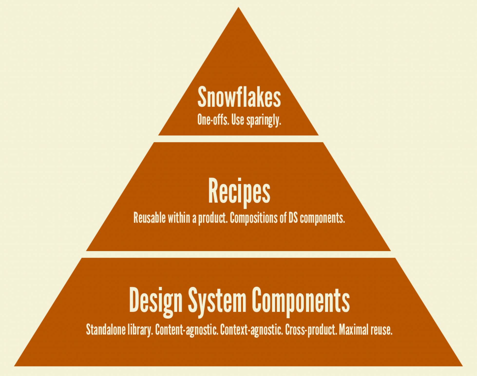
The second orientation is the layers at which components can be put in (see Figure 2). From many used components in the lower layer (design system components) to recipes (domain components outside the design sytem) to snowflakes (one-offs needed to build a product).
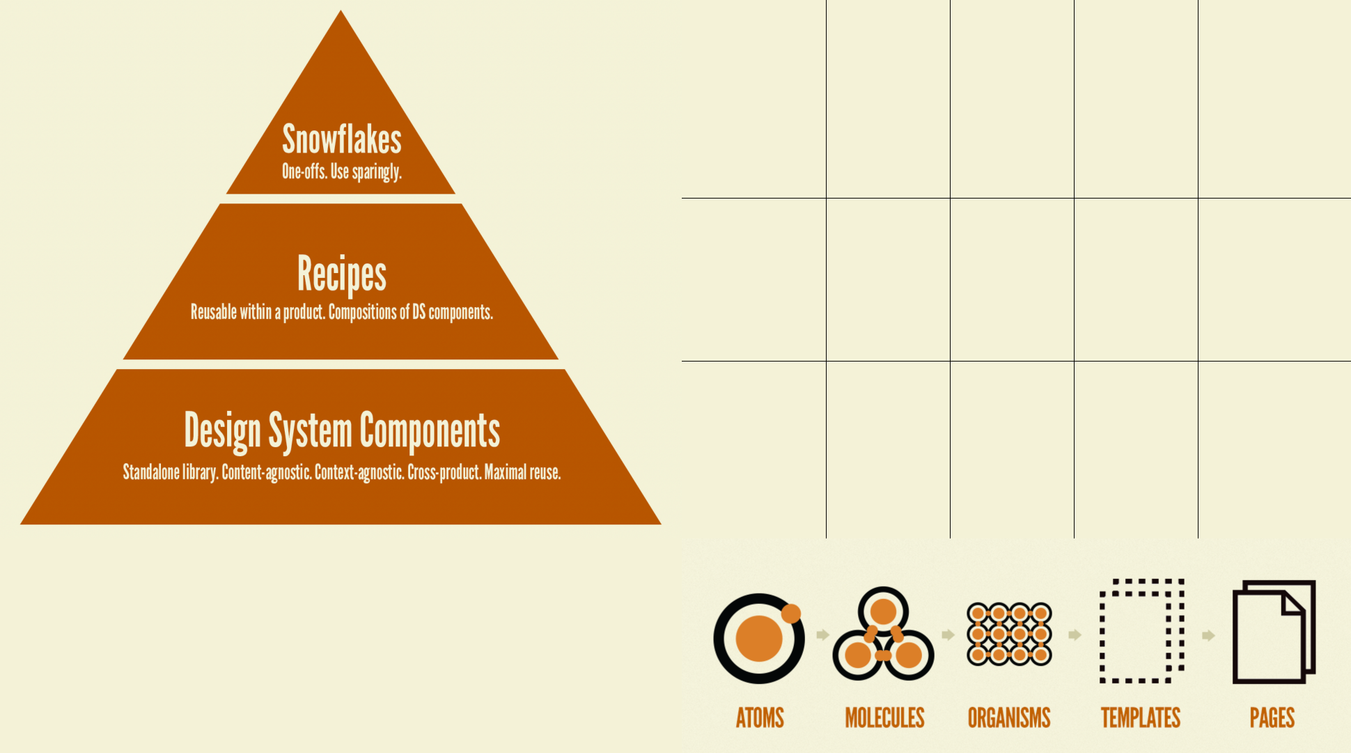
Now, I combined the two together to actually have two axis to form a grid to and place components on it (see Figure 3).
With that grid, it is now possible to mark those cells, in which the majority of components are living (see Figure 4).
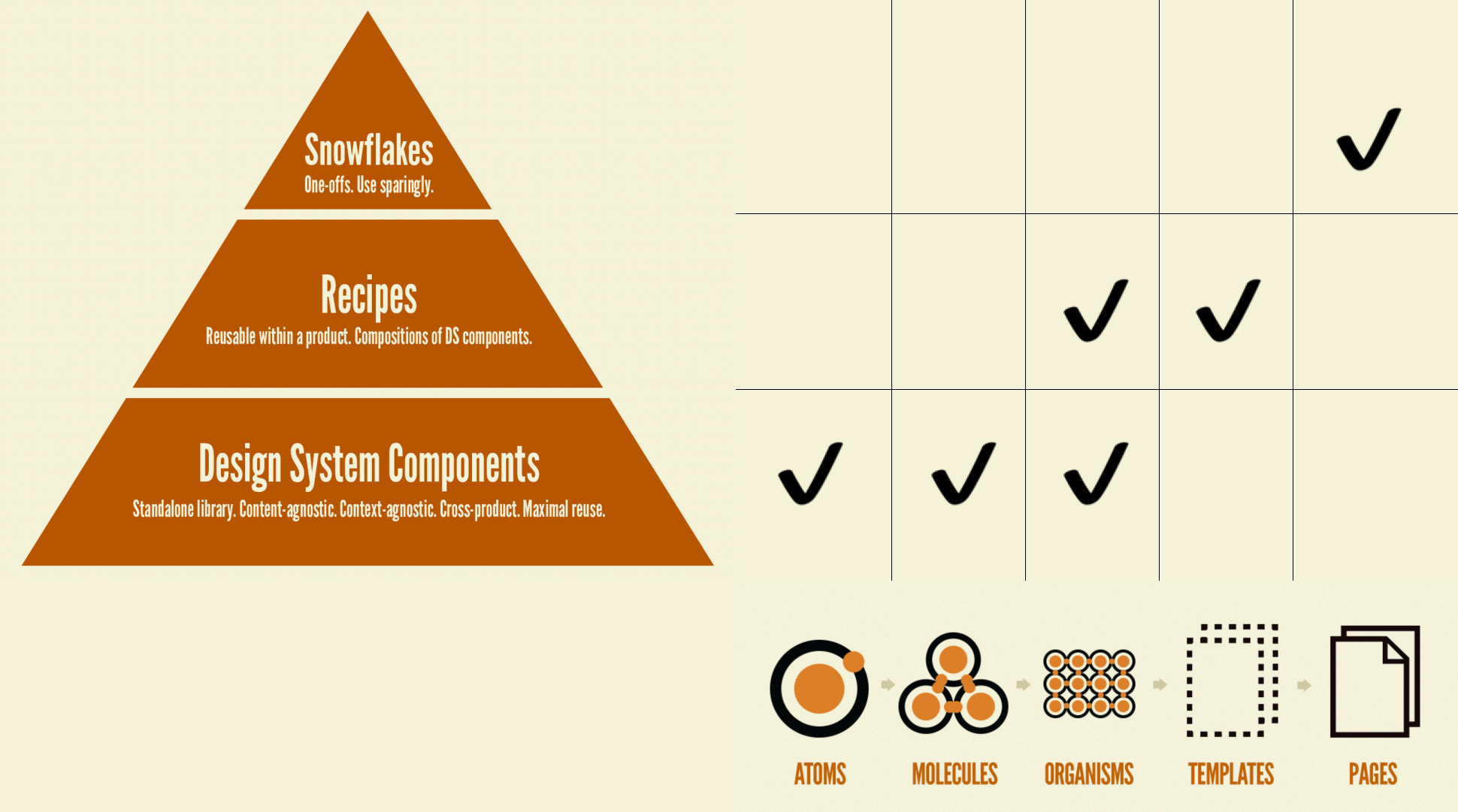
In the last step, it is now possible to draw zones around our markers, name these areas and provide rules or guidelines that components of that area shall comply with.
Example: Hokulea
A concrete example where that happened and how that can look like, is the Hokulea design system (a research project by the author of this).
First step to draw a grid on where components are aligned on a design system. Based on atomic design, the design system components are only atoms and molecules. Everything bigger than that goes into product level, which isn’t that much relevant for a design system. Next was to layer those components. Some internal layer, building blocks and the user-facing layer. From the Figma file below, the middle column is the most interesting one, as this is where component classes are identified.
It wasn’t yet not enough to understand what these components are (not) allowed to do. It wasn’t enough to draw rules or guidelines from that. This is where the second step for an in-depth investigation of the beforementioned middle column started, as shown in the next Figma file below. Placing the components on the canvas and after moving them around and drawing rectangles and removing the components there was time to make the boundaries across them visible.
With color-coding, proper areas and their names it was possible to understand what rules and guidelines for each of those components do apply.
-> Have a look at the component classifications from Hokulea and their guidelines.